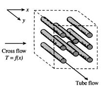
Cross Flow Heat Exchanger Equations
Heat exchangers have widespread industrial and domestic applications. Basic equations for the design of a plate heat exchanger.
When designing or reviewing heat 1600 Flue gas stream exchanger networks the Watersteam stream 1400 T-Q diagram gets useful.

. They proposed empirical correlations for a. The hot stream is marked with red color and the cold with blue color. The primary and secondary fluid in an heat exchanger process may.
Air stream The T-Q diagram is 1200. Žukauskas and Ulinskas experimentally studied the pressure drop and heat-transfer characteristics of the in-line and staggered tube bundles. Non-Regenerative Heat Exchanger The non-regenerative application is the most frequent and involves two separate fluids.
A heat exchanger is a heat transfer device that exchanges heat between two or more process fluids. Across a cylindrical wall the heat transfer surface area is continually increasing or decreasing. Effectiveness-NTU curves for different values of Cr Reference.
It can be seen that the effectiveness of newly TPMS compact crossflow heat exchanger is much higher than the analytical. Statics Force Analysis for Cylinder Supported by Two Rollers Equation and Calculator. The simplest heat exchanger is one for which the hot and cold fluids move in the same or opposite directions in a concentric tube or double-pipe construction.
In addition working through aerodynamic efficiency controlling acoustics and engaging in the next. Parallel and Counter-Flow Designs Parallel and Counter Flow heat exchanger Designs. The mean temperature difference in a heat transfer process depends on the direction of fluid flows involved in the process.
One common example of a heat exchanger is a cars radiator in which the hot coolant fluid is cooled by the flow of air over the radiators surface. In the counterflow arrangement of Figure 188b the. The figures shows the Effectiveness-NTU CFD results versus the cross flow heat exchanger analytical model where line plots illustrate the analytical data and symbol plots demonstrate the CFD results for the TPMS structures.
Heat Exchangers Transfer of heat is usually accomplished by means of a device known as a heat exchanger. The methodology employed for the design of a PHE is the same as for the design of a tubular heat exchanger. Flow in the same direction - parallel flow or co-current flow.
Examples of T-Q diagrams for a parallel flow heat exchanger left and a counter or cross flow heat exchanger middle. Heat transfer across a pipe or heat exchanger tube wall is more complicated to evaluate. Is the total heat exchanger surface area.
In the following figure you can see the curves to find the effectiveness of a cross flow heat exchanger for different values of NTU and C r. It is a measure of the heat exchangers departure from the ideal behavior of a counter flow heat exchanger having the same terminal temperatures. In parallel flow both fluids move in the same direction while transferring heat.
They are widely used in space heating refrigeration air conditioning power stations chemical plants petrochemical plants. Shear Stress in Shafts Calculator. Principal and Von-Mises Stress Equations and Calculator.
Mohrs Circle Equation and Calculator. The F-LMTD method is widely used in heat exchanger analysis particularly for heat exchanger selection sizing problems when as a result of the process requirements the temperatures are known and the size of the heat exchanger. In the opposite direction - counter-current flow.
Recuperates continuous heat flow hot and cold fluid are separated by a wallshell and tube heat exchangers 22 FLUID FLOW ARRANGEMENT a Co-current or parallel flow. Heat transfer across a rectangular solid is the most direct application of Fouriers law. The fluids can flow in the same direction through the equipment.
In the parallel-flow arrangement of Figure 188a the hot and cold fluids enter at the same end flow in the same direction and leave at the same end. Regenerators periodic heat flow hot and cold fluid alternately occupy the space of the heat exchanger g. Ln Counter-Flow Heat Exchanger For Cross-Flow and Shell-and-Tube Heat Exchangers.
A heat exchanger is a system used to transfer heat between a source and a working fluidHeat exchangers are used in both cooling and heating processes. Figure 3 is a cross-sectional view of a pipe constructed of a. 𝑐𝑐 ln Parallel-Flow Heat Exchanger 𝑙𝑙𝑚𝑚𝐶𝐶𝑃𝑃 𝑑𝑑.
Torsional Deformation and Stress of a Cross Shaft Equations and Calculator. The equations given in the present chapter are appropriate for the chevron type plates that are used in most industrial applications. Engineering 2D and 3D Statics Basics Equations and Calculators.
In counter flow the. Turbulent cross flow and heat transfer in tube bundles is a classical problem of shell and tube heat exchangers and has been investigated by many researchers. Accounting for vast changes in temperature like cold flows simulating heat exchanger profiles and optimizing their performance as well as examining the micro and nano-scale materials flowing through any system can all be on the plate of a thermal aerospace engineer.
The fluids may be separated by a solid wall to prevent mixing or they may be in direct contact. Common types of heat exchanger flows include parallel flow counter flow and cross flow. Many types of heat.
Or perpendicular to each other - cross flow.

Calculating Rate Of Heat Transfer In Parallel Flow Heat Exchangers Youtube
Comments
Post a Comment